Stage 7 – System / Integration Verification
Capstone Design
Imron Rosyadi
Stage 7 – System / Integration Verification
Capstone Design Course – From Needs to Validated Systems using the V‑Model & ISO/IEC/IEEE 29148
Focus of this session: Stage 7 – System / Integration Verification
DCP‑500B – System Verification
Session Learning Objectives
By the end of this session, you will be able to:
- Place Stage 7 – System / Integration Verification correctly in the V‑Model and distinguish it from Stage 6 and Stage 8.
- Describe the ISO/IEC/IEEE 29148 Verification process at the system level and its main activities.
- Explain what makes a good system‑level test: scenarios, interfaces, and non‑functional behavior.
- Identify the key deliverables of Stage 7, especially DCP‑500B – System Verification and
VER-*test artifacts. - Apply these ideas to ECE projects: IoT sensor systems, motor control platforms, FPGA‑accelerated pipelines, and mixed HW/SW systems.
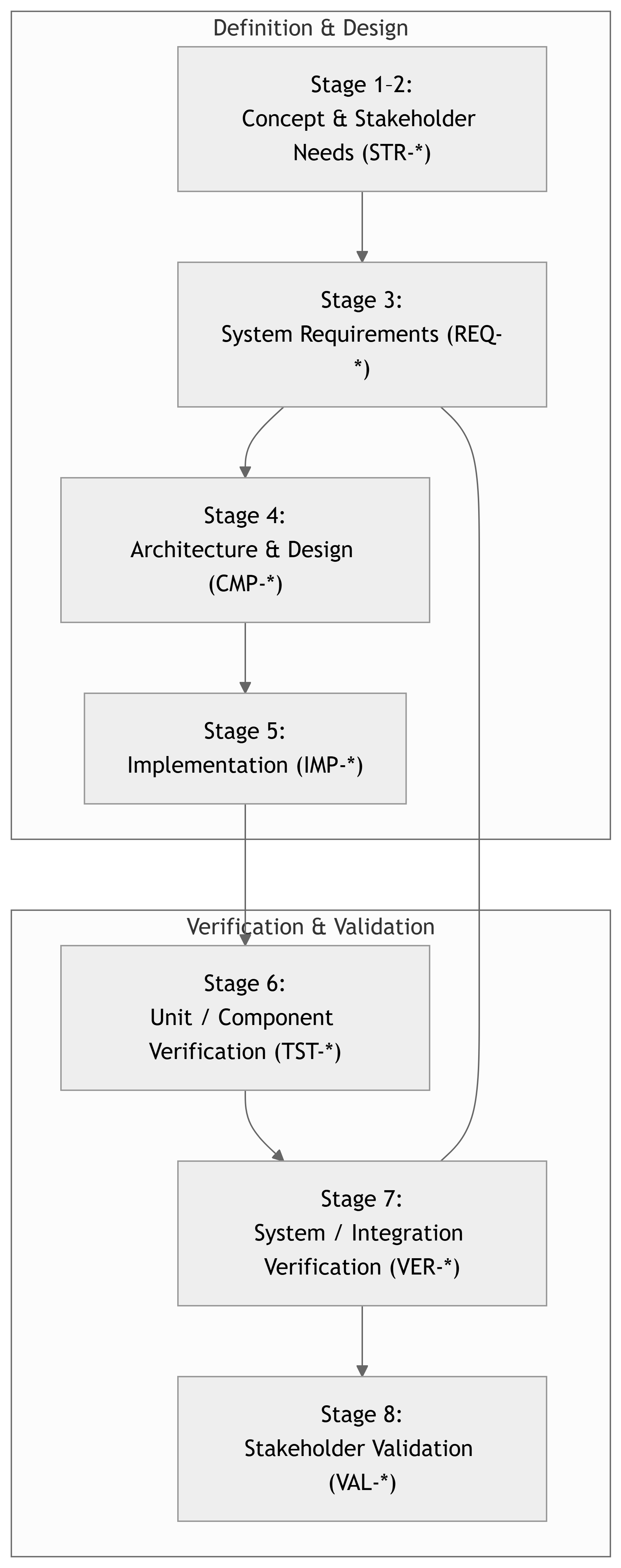
Where Are We in the V‑Model Now?
Note
Stage 7 is the mirror of Stage 3: You are verifying that the integrated system satisfies the system requirements (REQ-*).
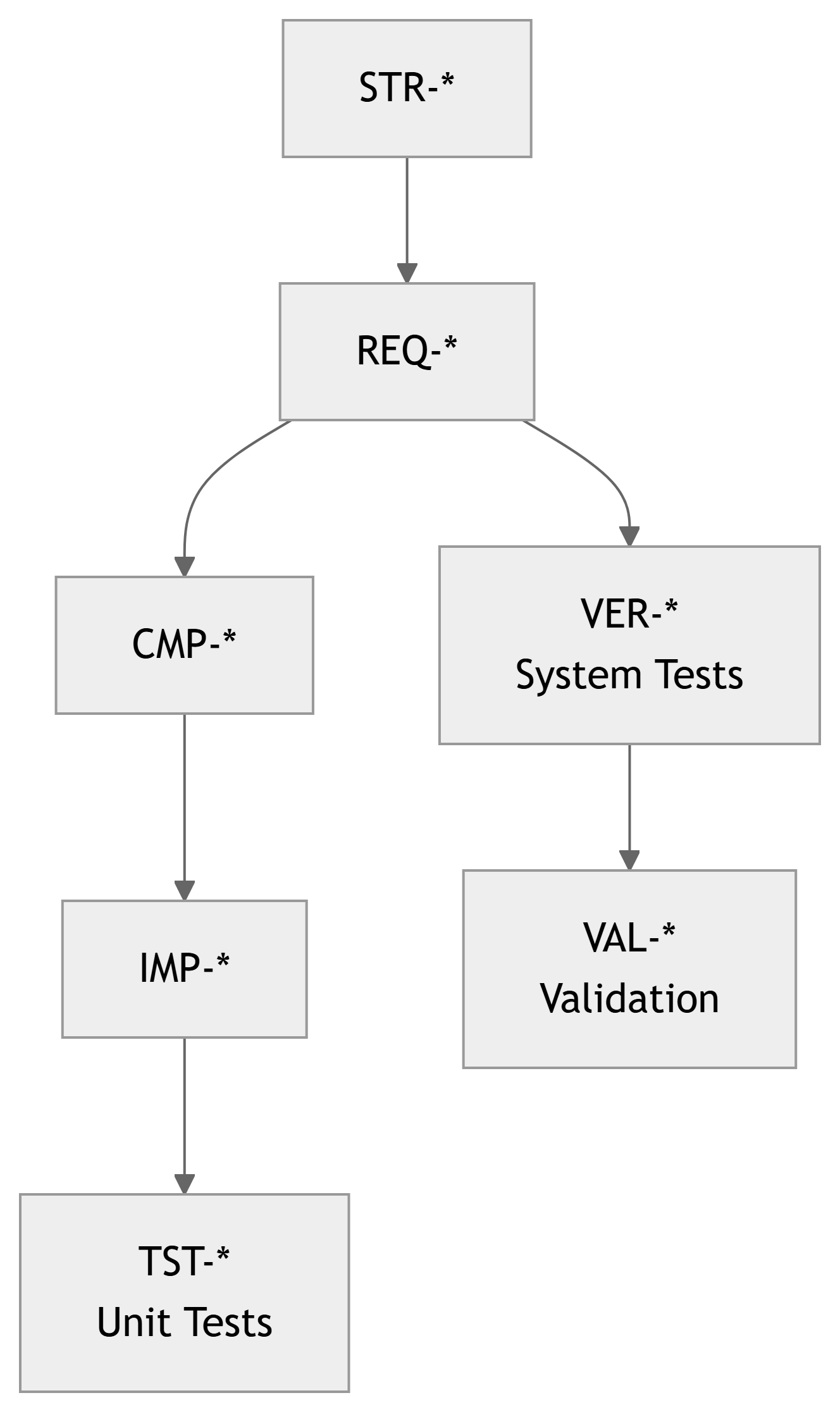
Recap: The Traceability Chain
Artifacts so far:
STR-*– Stakeholder requirements (Stage 2).REQ-*– System requirements (Stage 3).CMP-*– Components (Stage 4).IMP-*– Implementations (Stage 5).TST-*– Unit/component tests (Stage 6).
At Stage 7 we introduce:
VER-*– System / integration verification test cases.
Important
Stage 7 lives in the REQ-* ↔︎ VER-* space: Each system requirement should be covered by one or more VER-* tests.
Verification vs Validation – One More Time
- Verification – “Did we build it right?”
- Against requirements and design.
- Evidence: tests, analyses, inspections, simulations.
- Validation – “Did we build the right thing?”
- Against stakeholder needs & intended use.
At Stage 7, we are still doing verification:
- Verifying the integrated system against system requirements (
REQ-*). - Step before Stage 8, where actual users and realistic scenarios dominate.
Tip
Think of Stage 7 as:
“Can we prove that the system does everything the requirements document says, under realistic but controlled conditions?”
29148: System‑Level Verification Process
ISO/IEC/IEEE 29148 defines Verification as confirming that work products meet their specified requirements.
At the system level, that means:
- Plan verification of system requirements (
REQ-*). - Design system‑level test cases (
VER-*) that trace toREQ-*. - Establish the integration test environment (HW, SW, network, tools).
- Integrate components into a working system (HW + SW + data).
- Execute tests, record results as objective evidence.
- Evaluate coverage of requirements and handle non‑conformances.
- Update traceability and configuration status.

Stage 7 in the Course Framework
Course Stage:
- Stage 7 – System / Integration Verification
V‑Model Level:
- Right‑hand side, system‑level verification.
Inputs:
- DCP‑200 – System Requirements (
REQ-*). - DCP‑300 – Design (for context, expected interfaces).
- DCP‑400 – Implementation (
IMP-*, baselines). - DCP‑500A – Unit Verification results (
TST-*).
Outputs:
- Integrated system in test environment.
- System‑level test cases (
VER-*). - Test procedures, logs, and reports.
- Updated RTM with
REQ-* → VER-*links. - DCP‑500B – System Verification document.
Note
Stage 7 asks: > “Does the whole system meet its system requirements?”
Component vs System Verification – Quick Contrast
Stage 6 – Unit / Component Verification
- Scope: Single component in isolation or with simple stubs.
- Examples:
- A motor control firmware module.
- A FIR filter HDL core.
- A temperature sensor PCB on the bench.
- Main artifacts:
TST-*test cases.- DCP‑500A Unit Verification.
Stage 7 – System / Integration Verification
- Scope: Whole system, all major components integrated.
- Examples:
- Motor + controller + UI + comms.
- Sensor nodes + gateway + backend + dashboard.
- Main artifacts:
VER-*system test cases.- DCP‑500B System Verification.
Important
Unit tests ask: “Does this block work?” System tests ask: “Does the whole thing do what it’s supposed to do?”
29148 Activities – Applied to System Verification
System‑level verification activities (adapted from 29148):
- Identify verification scope
- Which system requirements (
REQ-*) will be verified in Stage 7.
- Which system requirements (
- Define verification objectives
- For each
REQ-*, specify how it will be verified (Test / Analysis / Modeling / Demonstration / Inspection).
- For each
- Design system test cases (
VER-*)- Inputs, environment, preconditions, execution steps, expected results.
- Prepare integration & test environment
- Hardware racks, network, lab setups, simulators, test data.
- Execute system tests
- Run tests, collect data, log outcomes.
- Evaluate & report
- Pass/fail per requirement.
- Coverage statistics (How many
REQ-*have at least oneVER-*?).
- Handle anomalies & regression
- Record defects, correct at system or component level, and re‑test.
DCP‑500B – System Verification (Overview)
Main Stage 7 deliverable:
- DCP‑500B – System Verification
Typical contents:
- Purpose and Scope – What is being verified at system level.
- System Under Test (SUT) – Architecture snapshot, configuration, versions.
- Test Environment & Tools – Lab setup, networks, simulators.
- System Test Cases (
VER-*) – definitions and links toREQ-*. - Execution Results – Summary + key logs and evidence.
- Defects / Issues & Resolutions – integration bugs, performance issues.
- Traceability & Coverage –
REQ-* ↔︎ VER-*. - Readiness for Validation (Stage 8) – Are we ready to show this to real users?
Note
DCP‑500B is the evidence package that your system fulfills its system requirements and is ready for stakeholder evaluation.
Mapping Requirements to System Tests
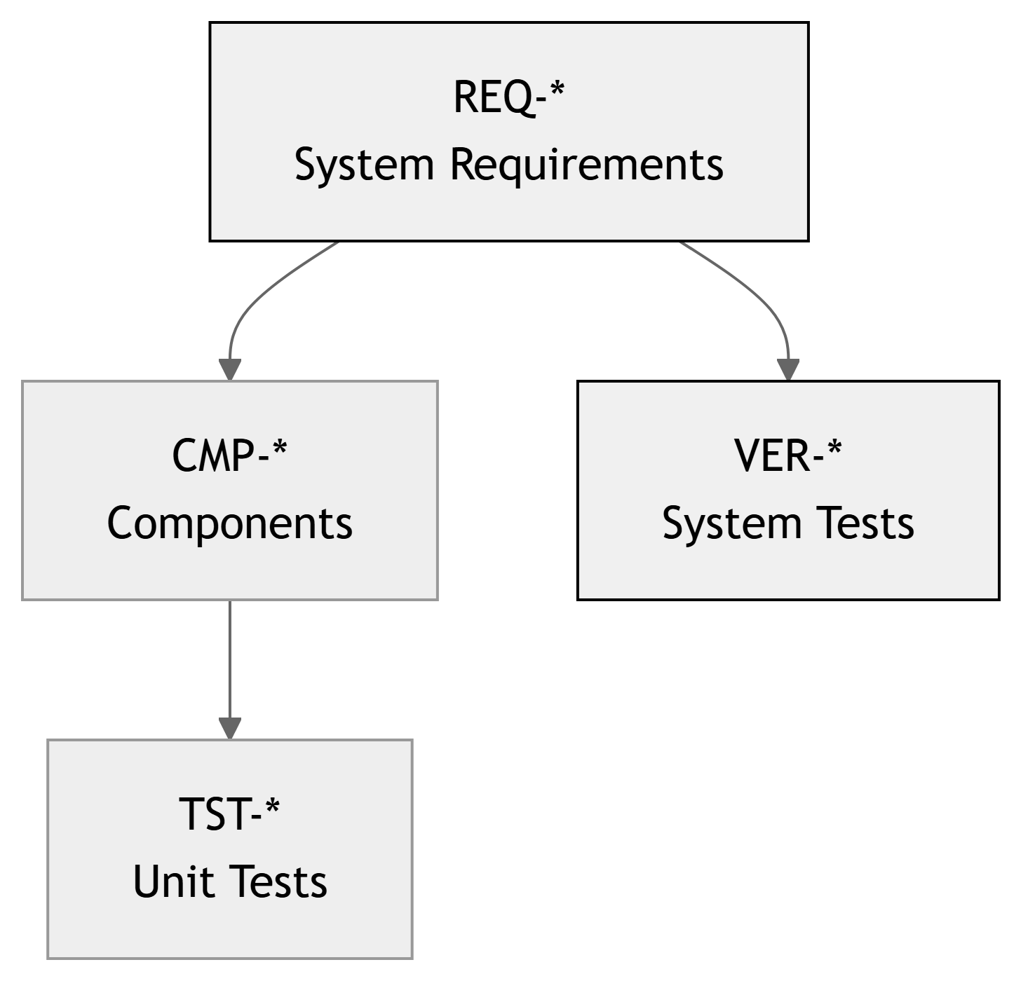
Interpretation:
- Each system requirement (
REQ-*) must be verified. - Some
REQ-*can be partially supported by unit tests (TST-*), but the final answer is at system level (VER-*). - The RTM should show coverage: every
REQ-*has at least oneVER-*(unless justified).
ECE Example 1 – Smart Lab Sensor Network (System Level)
Project Recap:
- Wireless sensor nodes in labs.
- Gateway forwards data to backend.
- Dashboard displays current values and alerts.
Relevant system requirements:
REQ-SY-011: Node measurements visible on dashboard within 30 s.REQ-SY-012: Data loss < 1% over 24 h.REQ-SY-013: System supports at least 20 nodes simultaneously.REQ-SW-020: Alerts raised when temperature > threshold.
System‑level tests (VER-*) might include:
VER-SYS-001: End‑to‑end latency from sensor change to dashboard update.VER-SYS-002: 24‑hour soak test for data loss and reliability.VER-SYS-003: Scalability test with 20 simulated or real nodes.VER-SYS-004: Alert behavior when lab overheats (alarm + log).
Example – VER‑SYS‑001: End‑to‑End Latency
Test Case ID: VER-SYS-001 – End‑to‑End Delay from Sensor to Dashboard
- Related Requirement(s):
REQ-SY-011: “System shall display updated lab temperature on the dashboard within 30 s of a step change.”
- System Under Test (SUT):
- N sensor nodes, 1 gateway, backend, dashboard UI.
- Method: Test (integrated system).
Setup:
- At least 1 node in demo lab with adjustable local temperature (e.g., using a hot air source).
- Backend and UI running in standard deployment configuration.
- PC screen capture or logging of dashboard timestamps.
Procedure:
- Wait for system to reach steady state at baseline temperature.
- At time
t0, apply a clear temperature step (e.g., raise sensor area from 22°C to ~30°C quickly). - Note the time when the node reading changes (based on internal logs or separate instrumentation).
- Observe dashboard; record time
t_dashboardwhen the new temperature first appears. - Compute
Δt = t_dashboard – t0. - Repeat for 5 trials.
Pass/Fail Criteria:
- For all trials:
Δt ≤ 30 s.
ECE Example 2 – Motor Drive Platform
Project Recap:
- Brushless DC motor drive with embedded controller and GUI.
Key system requirements:
REQ-SY-030: Motor reaches commanded speed within 1 s, overshoot < 10%.REQ-SY-031: Emergency stop halts motor within 200 ms.REQ-SY-032: Communication fault detection within 500 ms, safe state on error.
System‑level VER-* tests:
VER-SYS-030-01: Step speed command from 0 → 2000 RPM, measure speed vs time.VER-SYS-031-01: Trigger E‑stop while spinning at 1500 RPM, measure stop time.VER-SYS-032-01: Simulate CAN link failure and observe safe‑state transition.
Example – VER‑SYS‑031‑01: Emergency Stop
Test Case ID: VER-SYS-031-01 – Emergency Stop Response
- Related Requirement(s):
REQ-SY-031: “Emergency stop shall bring the motor to a halt within 200 ms from activation under any normal operating condition.”
- SUT:
- Full motor drive system (motor, power board, controller, E‑stop hardware).
- Method: Test (physical measurement).
Setup:
- Motor mounted securely with appropriate load.
- Current and speed measurement (e.g., encoder + oscilloscope).
- E‑stop button wired as per design.
Procedure:
- Command motor to steady 1500 RPM.
- Using a digital IO or scope trigger, activate E‑stop and simultaneously mark
t0. - Record motor speed vs time (via encoder or tachometer).
- Determine
t_stop, when speed reaches ~0 RPM (below a threshold). - Compute
Δt = t_stop – t0. - Repeat for speeds 500, 1000, 1500, 2000 RPM (or range defined in DCP‑200).
Pass/Fail Criteria:
- For all tested speeds,
Δt ≤ 200 ms.
ECE Example 3 – FPGA‑Accelerated Signal Processing Chain
Project Recap:
- FPGA card performs filtering and decimation; host PC handles control and logging.
System requirements might include:
REQ-SY-040: End‑to‑end processing latency ≤ 5 ms.REQ-SY-041: Throughput ≥ 48 k samples/s.REQ-SY-042: Output SNR ≥ 60 dB with specified input.
System‑level VER-* tests:
VER-SYS-040-01: Latency test from analog input change to processed data on host.VER-SYS-041-01: Throughput test with continuous data and back‑to‑back frames.VER-SYS-042-01: End‑to‑end SNR test with reference input (e.g., pure tone + noise).
Designing Good System Tests – Key Qualities
Good VER-* system tests are:
- Requirements‑driven:
- Explicitly reference
REQ-*IDs; not just “general poking around.”
- Explicitly reference
- Scenario‑based:
- Reflect realistic use cases or operational scenarios (e.g., 24‑hour operation, network outage, overload).
- Observable:
- System outputs and behaviors are measurable and recorded (logs, waveforms, screenshots).
- Repeatable:
- Clear setup and procedure to re‑run the same scenario for regression.
- Cross‑component:
- Involve multiple subsystems: HW, FW, SW, networking, UI.
Tip
Ask yourself:
“If I change a firmware version, can I re‑run this VER-* test and see if the system still meets the same requirement?”
Test Methods (TAMDI) at System Level
As in Stage 6, 29148 supports multiple verification methods:
- Test – Execute the system and measure behavior (most Stage‑7 work).
- Analysis – Use models, math, or logs to argue that behavior meets requirements.
- Modeling/Simulation – Digital twins, network simulators, etc.
- Demonstration – Qualitative show‑and‑tell (often not sufficient alone).
- Inspection – Check configuration, documentation, or interfaces manually.
Examples for Stage 7:
- Use Test to check: latency, throughput, response to faults.
- Use Analysis to show: worst‑case timing margins from logs.
- Use Inspection to verify: configuration files match documented settings.
System Test Environment & Configuration
You must define and control the environment in which system tests run.
Example for Smart Lab Sensor Network:
- Hardware:
- 5 real sensor nodes + optional simulated nodes.
- 1 gateway, 1 backend server (lab PC or VM).
- Router / Wi‑Fi AP if needed.
- Software:
- Backend at baseline tag
backend-v0.7-stage7. - Node firmware
node-fw-v1.0-stage7. - UI
labdash-ui-v1.0-stage7.
- Backend at baseline tag
- Network / Infrastructure:
- Lab VLAN isolated from other networks.
- Time‑synchronized clocks (NTP) for consistent timestamps.
- Test Tools:
- Traffic generator or script to simulate node load.
- Log collectors, dashboards, metrics exporters.
Note
System verification depends heavily on having a stable, reproducible environment. Document it in DCP‑500B.
DCP‑500B – Example Structure (Short)
- Introduction & Scope
- Which requirements and scenarios are covered by this system verification.
- System Under Test (SUT)
- Architecture overview, versions of HW/SW, configuration.
- Test Environment & Tools
- Lab topology, equipment, simulators, logging.
- System Test Cases (
VER-*)- Detailed definitions: objective, method, setup, procedure, pass/fail criteria.
- Test Execution & Results
- Summary and key evidence.
- Defects & Integration Issues
- Failures, root cause, fixes, retests.
- Requirements Coverage & RTM Update
- How many
REQ-*covered byVER-*, any gaps.
- How many
- Readiness for Validation (Stage 8)
- Are we ready to put this in front of real stakeholders?
Example – System Test Summary Table
| VER ID | REQ ID(s) | Method | Status | Notes |
|---|---|---|---|---|
| VER-SYS-001 | REQ-SY-011 | Test | PASS | Latency 8–12 s (limit 30 s) |
| VER-SYS-002 | REQ-SY-012 | Test | PASS | Data loss < 0.1% over 24 h |
| VER-SYS-003 | REQ-SY-013 | Test + Analysis | FAIL | 20 nodes overload backend CPU |
| VER-SYS-004 | REQ-SW-020 | Test | PASS | Alerts triggered correctly |
| VER-SYS-005 | REQ-SY-0xy (power) | Test + Analysis | PASS | System average power < specified budget |
Warning
Failing a system test is common, especially initially. The important thing is: - Capture it, understand it, and use it to improve.
Defects and System‑Level Root Cause
When a VER-* test fails, Stage 7 should:
- Log the defect with links:
VER-*,REQ-*, affectedCMP-*/IMP-*. - Analyze the root cause:
- Integration issue?
- Single component bug that escaped Stage 6?
- Misunderstood requirement?
- Fix at appropriate level:
- Could require changes to: firmware, backend, UI, or configuration.
- Regression test:
- Re‑run the failing
VER-*and any related tests.
- Re‑run the failing
Tip
Use the same issue tracker discipline from Stage 6, but now defects can involve multiple components.
RTM with VER-* – Example Excerpt
| STR ID | REQ ID | CMP IDs | TST IDs (Stage 6) | VER IDs (Stage 7) | Notes |
|---|---|---|---|---|---|
| STR-SY-001 | REQ-SY-010 | CMP-SY-040, SW-020 | TST-SY-040-01, SW-020-01 | VER-SYS-001 | End‑to‑end accuracy & latency |
| STR-SY-002 | REQ-SY-011 | CMP-SW-020, SW-030, SW-010 | TST-SW-020-02 | VER-SYS-001, VER-SYS-002 | End‑to‑end reporting and reliability |
| STR-SY-003 | REQ-SY-013 | CMP-SW-030, SW-010 | — | VER-SYS-003 | Capacity test only at system level |
| STR-SY-004 | REQ-SW-020 | CMP-SW-030, SW-010 | TST-SW-030-01 | VER-SYS-004 | Alerts end‑to‑end |
Important
By the end of Stage 7, every REQ-* should either:
- Have at least one
VER-*test marked PASS, or - Have a documented rationale (e.g., waived, not applicable to prototype).
In‑Class Exercise – Draft a System‑Level Test
Activity (5–10 minutes):
- Pick one system requirement (
REQ-*) from your team’s DCP‑200. - Identify which components participate in fulfilling it.
- Draft a system test case (
VER-*) that:- Has a clear objective.
- Defines environment / setup.
- Describes 4–6 procedure steps.
- States measurable pass/fail criteria.
Examples of good candidates:
- Latency / response time requirement.
- Throughput / capacity requirement.
- Robustness to network loss or power cycling.
Note
We’ll ask a few teams to share their VER-* ideas and map them to REQ-* on the board.
Summary – Key Takeaways for Stage 7
- Stage 7 – System / Integration Verification checks the integrated system against system requirements (
REQ-*), per ISO/IEC/IEEE 29148. - System tests (
VER-*) are:- Requirements‑driven, scenario‑based, cross‑component, and repeatable.
- The main deliverable is DCP‑500B – System Verification, capturing:
- System under test, environment,
VER-*cases, results, defects, and coverage.
- System under test, environment,
- Traceability expands: the RTM links
REQ-*toVER-*(and also toTST-*where helpful). - A solid Stage 7 greatly reduces risk when you enter Stage 8 – Stakeholder Validation and public demos.
Important
If Stage 6 is about building strong bricks, Stage 7 is about checking that the house built from those bricks is safe, functional, and matches the blueprint.