Stage 6 – Unit / Component Verification
Capstone Design
Imron Rosyadi
Stage 6 – Unit / Component Verification
Capstone Design Course – From Needs to Validated Systems using the V‑Model & ISO/IEC/IEEE 29148
Focus of this session: Stage 6 – Unit / Component Verification
DCP‑500A – Unit Verification
Session Learning Objectives
By the end of this session, you will be able to:
- Explain where Stage 6 fits in the V‑Model and how it differs from Stage 7 (System Verification).
- Describe the ISO/IEC/IEEE 29148 Verification process at the component level and its main activities.
- Define unit / component verification vs informal “it seems to work” testing.
- Identify the key deliverables of Stage 6, especially DCP‑500A Unit Verification and
TST-*artifacts. - Apply these ideas to ECE examples such as embedded firmware modules, FPGA IP cores, and hardware subassemblies.
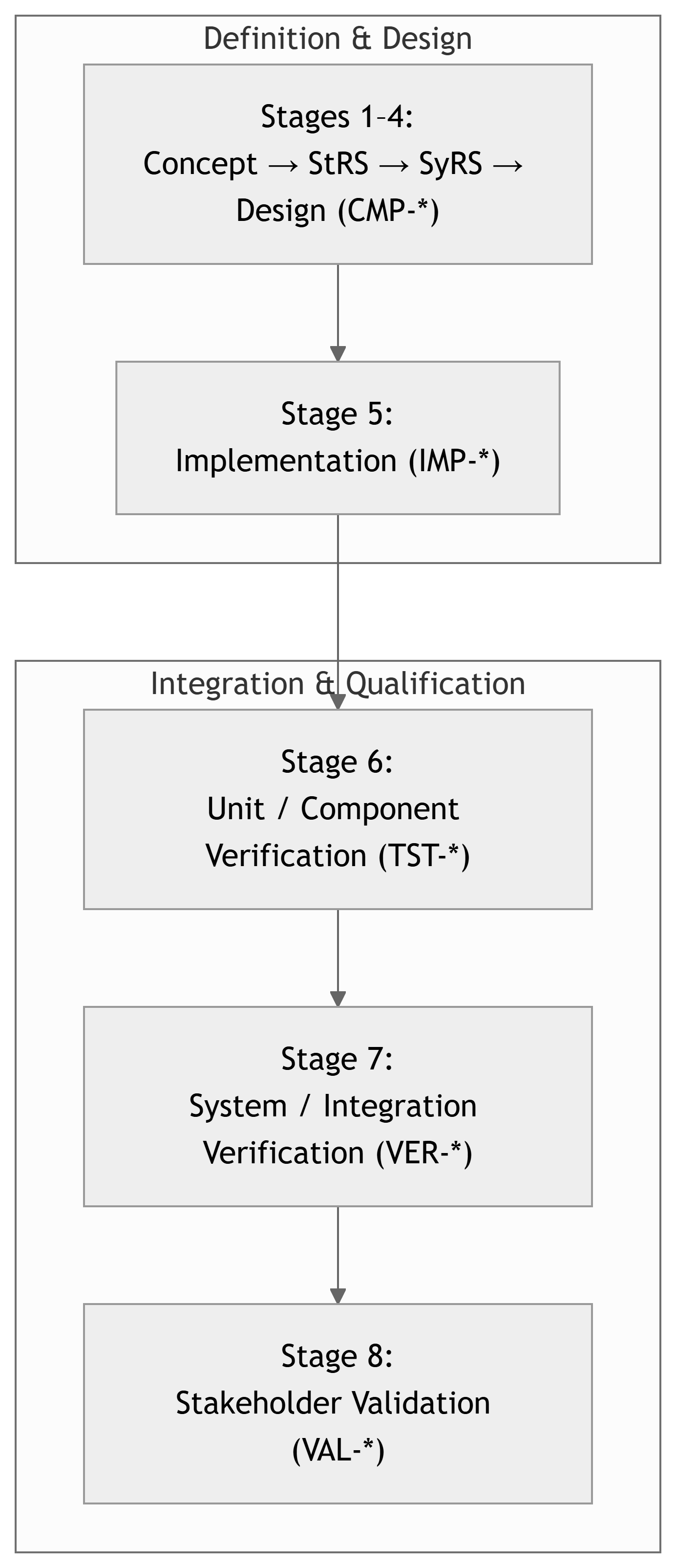
Where Are We in the V‑Model?
Note
Stage 6 sits on the right‑hand side, directly across from Stage 4 (Design). You are testing individual components against their design specs and allocated requirements.
Quick Recap – Traceability Backbone
Traceability chain:
STR-*– Stakeholder RequirementsREQ-*– System RequirementsCMP-*– Components (design elements)IMP-*– Implementation items (code, boards, FPGA, etc.)TST-*– Unit / component tests (Stage 6)VER-*– System verification tests (Stage 7)VAL-*– Validation activities (Stage 8)
All maintained in the RTM.
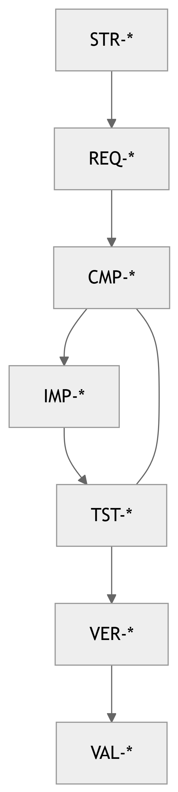
Important
Stage 6 lives in the CMP-* ↔︎ TST-* space: Every component should have planned, traceable tests.
Verification vs Validation (Revisited)
- Verification – “Did we build it right?”
- Against requirements and design specs.
- Evidence‑based: tests, analysis, inspection, etc.
- Validation – “Did we build the right thing?”
- Against stakeholder needs and intended use.
At Stage 6, we are doing verification at the unit / component level:
- Verifying that each component (
CMP-*) + implementation (IMP-*) behaves as its specification says.
Tip
Think: “Does this module do exactly what its component spec and allocated requirements say it should?”
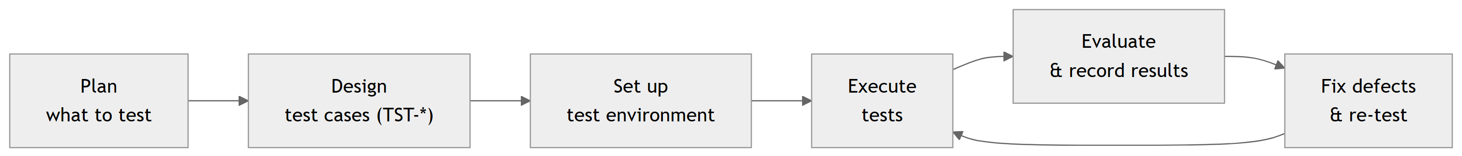
29148: Verification Process at Component Level
ISO/IEC/IEEE 29148 describes Verification as a process to confirm that work products meet their specified requirements.
At component level, this means:
- Plan verification for each component.
- Design test cases linked to requirements and design elements.
- Establish test environment (tools, equipment, simulators).
- Execute tests and record objective evidence.
- Evaluate results and decide pass/fail for each requirement.
- Record and track defects, and re‑test after fixes.
Stage 6 in the Course Framework
Course Stage:
- Stage 6 – Unit / Component Verification
V‑Model Level:
- Lower‑right: unit tests / component verification
Inputs:
- Approved DCP‑300 Design (component specs, interfaces).
- Approved DCP‑400 Implementation (actual HW/SW built,
IMP-*). - Initial Test Plan from Stage 4.
Outputs:
TST-*unit/component test cases.- Test procedures and logs.
- Defect / issue reports and resolutions.
- Updated RTM (
CMP-* → TST-*). - DCP‑500A – Unit Verification document.
Note
Stage 6 asks: > “Is each building block solid before we snap them together in Stage 7?”
Component Verification vs System Verification
Stage 6 – Unit / Component Verification
- Test individual components (
CMP-*) and their implementations (IMP-*). - Example scope:
- A single firmware module (e.g., motor control loop).
- A single FPGA IP core (e.g., FIR filter).
- A hardware board in isolation (e.g., sensor PCB).
- Focus:
- Does this unit meet its spec?
- Does it behave correctly across specified ranges?
Stage 7 – System / Integration Verification
- Test the integrated system.
- Example scope:
- Motor controller + UI + communication.
- Full sensor network (nodes + gateway + backend).
- Focus:
- Does the system satisfy system requirements (
REQ-*)? - Are interfaces and timing working correctly together?
- Does the system satisfy system requirements (
Important
Unit tests try to isolate the component under test. System tests exercise end‑to‑end flows.
29148 Activities – Applied to Components
29148 Verification Activities (adapted to Stage 6):
- Identify verification items
- Choose which components (
CMP-*) and implementation items (IMP-*) need unit tests.
- Choose which components (
- Define verification objectives
- For each item, state which requirements (
REQ-*) or design constraints you are verifying.
- For each item, state which requirements (
- Design test cases (
TST-*)- Preconditions, inputs, expected outputs, pass/fail criteria.
- Specify test methods & tools
- Hardware bench, HDL simulator, unit test framework, logic analyzer, etc.
- Execute tests
- Run tests, record procedures, outputs, and anomalies.
- Evaluate & report
- Declare each test Pass/Fail, tie failures to defect reports/buttons in issue tracker.
- Regression
- Re‑run relevant tests after fixes or design changes.
DCP‑500A – Unit Verification (Overview)
Main Stage 6 deliverable:
- DCP‑500A – Unit Verification
Typical contents:
- Scope & Objectives
- Items Under Test (IUTs) – Components /
CMP-*andIMP-*. - Test Environment & Tools
- Unit Test Cases (
TST-*) – definitions. - Test Execution Results – logs & summaries.
- Defects & Resolutions
- Updated RTM excerpt (
CMP-* ↔︎ TST-*) - Conclusion: Readiness for System Verification (Stage 7)
Note
DCP‑500A is the evidence package that your components are ready to be integrated.
From Components to Unit Tests – Mapping
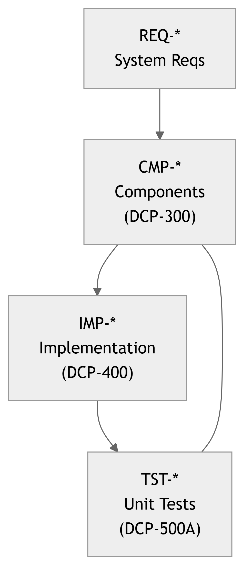
Interpretation:
- Each
CMP-*is allocated someREQ-*. - Each
CMP-*is realized by one or moreIMP-*. - For each critical
CMP-*, you design one or moreTST-*that:- Exercise the implementation.
- Show that allocated requirements are satisfied.
ECE Example 1 – Embedded Motor Controller (Unit Level)
Project Recap:
BLDC motor controller for a small robot arm.
Relevant items:
REQ-SY-010: Motor speed control 0–3000 RPM, ±2% accuracy.CMP-SW-020: Motor control firmware module.IMP-SW-020A:motor_ctrl.c,motor_ctrl.h.
What do we verify at Stage 6?
- Control module’s speed regulation behavior.
- Response to step changes in speed command.
- Handling of sensor faults (e.g., encoder dropout).
Example Unit Tests (TST-*):
TST-SW-020-01:- Objective: Verify speed control accuracy at several setpoints.
- Method: HIL (hardware‑in‑the‑loop) testbench with actual motor.
TST-SW-020-02:- Objective: Verify controller response to speed step input.
- Method: Log speed vs time; check settling time < 0.5 s, overshoot < 10%.
TST-SW-020-03:- Objective: Verify safe behavior on encoder signal loss.
- Method: Simulate encoder failure; ensure motor stops within 200 ms.
Example – Motor Controller Test Case Definition
Test Case ID: TST-SW-020-01 – Speed Control Accuracy
- Related Requirement(s):
REQ-SY-010– Speed 0–3000 RPM with ±2% accuracy.
- Related Component / Implementation:
CMP-SW-020– Motor control firmware module.IMP-SW-020A–motor_ctrl.c/motor_ctrl.h.
- Test Method: Test (physical, instrumented).
- Test Setup:
- BLDC motor with encoder.
- Motor controller board with firmware
motor-fw-v1.0-TST. - Lab PSU, oscilloscope, tachometer (or encoder‑based RPM measurement).
Procedure:
- Set PWM frequency and control gains as in DCP‑300, Appendix B.
- Command setpoints: 500, 1500, 2500, 3000 RPM via serial console.
- For each setpoint, wait until speed stabilizes (t > 2 s).
- Measure actual RPM (average over 1 s window).
- Compute error = |actual – setpoint| / setpoint × 100%.
Pass/Fail Criteria:
- All tested setpoints must have error ≤ 2%.
Result:
[To be filled after execution – e.g., “PASS – max error = 1.3% at 3000 RPM”]
ECE Example 2 – FPGA‑Based FIR Filter
Project Recap:
FPGA card performing real‑time FIR low‑pass filtering.
Relevant items:
REQ-SY-020: Low‑pass FIR with 60 dB stop‑band at 8 kHz, fs = 48 kHz.CMP-HW-010: FPGA filter core.IMP-HW-010A: HDL modulefir_core.vhd.
Stage‑6 Focus:
- Verify functional correctness of
fir_core. - Measure frequency response and numerical precision.
Example Unit Tests (TST-*):
TST-HW-010-01:- Method: HDL simulation.
- Objective: Check impulse response matches design coefficients exactly.
TST-HW-010-02:- Method: HDL simulation with sinusoidal sweeps.
- Objective: Verify magnitude response:
- Pass‑band ripple ≤ 1 dB.
- Stop‑band attenuation ≥ 60 dB beyond 8 kHz.
TST-HW-010-03:- Method: Simulation with max‑amplitude signals.
- Objective: Check no overflow or saturation within expected input range.
ECE Example 3 – Sensor Node Hardware (Smart Lab Project)
Project Recap:
Smart Lab wireless sensor nodes.
Relevant items:
REQ-SY-010: Temperature measurement 10–40°C, ±0.5°C.CMP-SY-040: Sensor node hardware.IMP-SY-040A: Node PCB rev B.
Stage‑6 Hardware Verification:
- Verify sensor accuracy and linearity.
- Verify power rails within tolerance.
- Verify radio front‑end basic operation (RSSI, packet send/receive at unit level).
Example Unit Tests (TST-*):
TST-SY-040-01: Temperature sensor calibration and accuracy bench test.TST-SY-040-02: Power integrity test – verify 3.3 V rail under load stays within ±5%.TST-SY-040-03: RF smoke test – verify node can send packets to test receiver over 5 m line‑of‑sight with RSSI above threshold.
Designing Good Unit Tests – 29148‑Style
Characteristics of good unit/component tests:
- Traceable:
- Linked to specific
REQ-*andCMP-*.
- Linked to specific
- Repeatable:
- Clear procedure and environment description.
- Observable:
- You can capture outputs or measurements objectively.
- Deterministic:
- Same preconditions → same expected result (within defined tolerance).
- Isolated (as far as practical):
- Minimize external dependencies; use stubs/mocks when needed.
Tip
Ask yourself for each unit test:
“If someone else on my team followed this procedure, would they get the same pass/fail decision?”
Test Methods – TAMDI at Component Level
29148 and many SE texts use TAMDI test methods:
- Test – Run the system/component and directly measure behavior.
- Analysis – Use models, calculations, or code review to infer behavior.
- Modeling/Simulation – Computer‑based experiments (e.g., HDL simulation).
- Demonstration – Show the function informally, usually qualitative.
- Inspection – Visual/manual check (e.g., schematics, code, layout).
At Stage 6:
- You will mostly use Test and Modeling/Simulation, sometimes Inspection and Analysis.
- Example:
- Inspect a PCB layout to confirm trace widths (Inspection).
- Simulate a filter’s frequency response (Modeling/Simulation).
- Run firmware unit tests in CI (Test).
Test Environment & Tooling
For Stage 6, you must define a test environment to support unit/component tests.
Examples for ECE projects:
- Embedded firmware:
- Target dev boards, JTAG/SWD debuggers.
- UART/USB link to PC for scripts to drive tests.
- Unit test frameworks (Unity, Google Test on host).
- FPGA/HDL:
- HDL simulation tools (Vivado, Questa).
- Testbench code that feeds stimuli and checks responses.
- Analog / mixed‑signal / RF boards:
- Oscilloscope, function/signal generator, DMM, spectrum analyzer.
- Test fixtures to connect loads and probes consistently.
Note
Document versions and configurations of test tools, just as you do for implementation tools.
Sample DCP‑500A Structure (Short Version)
- Introduction and Scope
- Which components and requirements are covered.
- Items Under Test (IUTs)
- List of
CMP-*andIMP-*under unit test.
- List of
- Test Environment and Tools
- Hardware bench, simulators, etc.
- Unit Test Cases (
TST-*)- Tables / subsections with objectives, inputs, expected results.
- Execution Summary
- Counts of tests passed/failed/skipped.
- Defects and Anomalies
- Issues discovered, mapped to tests and components.
- Traceability Updates
CMP-* ↔︎ TST-*mapping in RTM.
- Readiness for Stage 7
- Statement about which components are verified and ready to integrate.
Example – Unit Test Summary Table (Excerpt)
| TST ID | CMP ID | REQ ID(s) | Method | Result | Notes |
|---|---|---|---|---|---|
| TST-SW-020-01 | CMP-SW-020 | REQ-SY-010 | Test (HIL) | PASS | Max error 1.3% at 3000 RPM |
| TST-SW-020-02 | CMP-SW-020 | REQ-SY-010 | Test (HIL) | PASS | Settling time < 0.4 s |
| TST-HW-010-01 | CMP-HW-010 | REQ-SY-020 | Simulation | PASS | Impulse response correct |
| TST-HW-010-02 | CMP-HW-010 | REQ-SY-020 | Simulation | FAIL | Stop‑band 55 dB only |
| TST-SY-040-01 | CMP-SY-040 | REQ-SY-010 | Test (bench) | PASS | ±0.4°C across range |
Warning
A FAIL is not a disaster; hiding it is. Failures are where engineering actually happens.
Defects, Root Cause, and Re‑Testing
When a test fails, Stage 6 should:
- Log the defect
- ID it, link to
TST-*,CMP-*,IMP-*, and relevantREQ-*.
- ID it, link to
- Classify severity
- Blocking vs non‑blocking for integration.
- Analyze root cause
- Is it implementation? design? requirement? measurement error?
- Fix and re‑test
- Update code / HDL / hardware as needed.
- Re‑execute affected tests (and regression tests).
- Update documents & RTM
- If design/requirements change, follow change control.
Tip
Use your issue tracker with tags like defect, unit-test-fail, and include IDs such as TST-SW-020-02, CMP-SW-020.
In‑Class Exercise – Draft a Unit Test Case
Activity (5–10 minutes):
- Pick one component (
CMP-*) from your team’s design (Stage 4). - Identify one requirement (
REQ-*) that was allocated to this component. - Draft a unit test case (
TST-*) with:- Objective.
- Method (Test / Simulation / etc.).
- Setup (equipment/software).
- Procedure (3–5 bullet steps).
- Pass/fail criteria (quantitative if possible).
Example prompt answers on the board:
CMP-SW-015– Data logger module.REQ-SW-033– “System shall store at least 10,000 records in non‑volatile memory without data corruption.”TST-SW-015-01– Fill log with 10,000 entries, power‑cycle 50 times, check for bit‑exact match.
Note
This exercise primes their thinking for drafting DCP‑500A in their own projects.
Summary – Key Takeaways for Stage 6
- Stage 6 is about Unit / Component Verification: proving that each component (
CMP-*) and its implementation (IMP-*) satisfies its allocated requirements. - ISO/IEC/IEEE 29148 Verification process at component level involves:
- Planning tests, designing
TST-*, executing them in a defined environment, and recording objective evidence.
- Planning tests, designing
- All unit tests should be traceable:
REQ-* → CMP-* → IMP-* → TST-*. - The main deliverable is DCP‑500A Unit Verification, which documents:
- Items under test, test environment, test cases, results, and defects.
- Solid Stage‑6 verification reduces risk and effort in Stage 7 System / Integration Verification and Stage 8 Validation.
Important
Do not skip Stage 6 or treat it as an afterthought. A strong unit verification phase is one of the clearest markers of professional‑grade engineering practice.