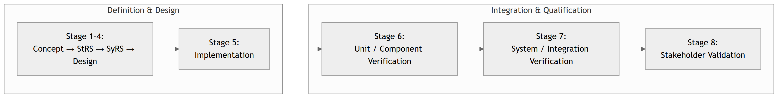
Stage 5 – Implementation / Construction
Capstone Design
Standards View: 15288 & 29148 at Stage 5
ISO/IEC/IEEE 15288 – System Life Cycle Processes
Relevant processes for Stage 5:
- Implementation Process
- Transform system element specifications into realized system elements (code, boards, FPGA bitstreams, etc.).
- Confirm that each implementation corresponds to its design description.
- Configuration Management Process
- Establish and control configuration items (CIs).
- Manage baselines, versions, and changes.
- Ensure the correct items are used in integration, test, and deployment.
ISO/IEC/IEEE 29148 – Requirements Engineering
- Still relevant in Stage 5 because:
- Requirements guide what to implement.
- Requirement changes must be controlled (change requests, impact analysis).
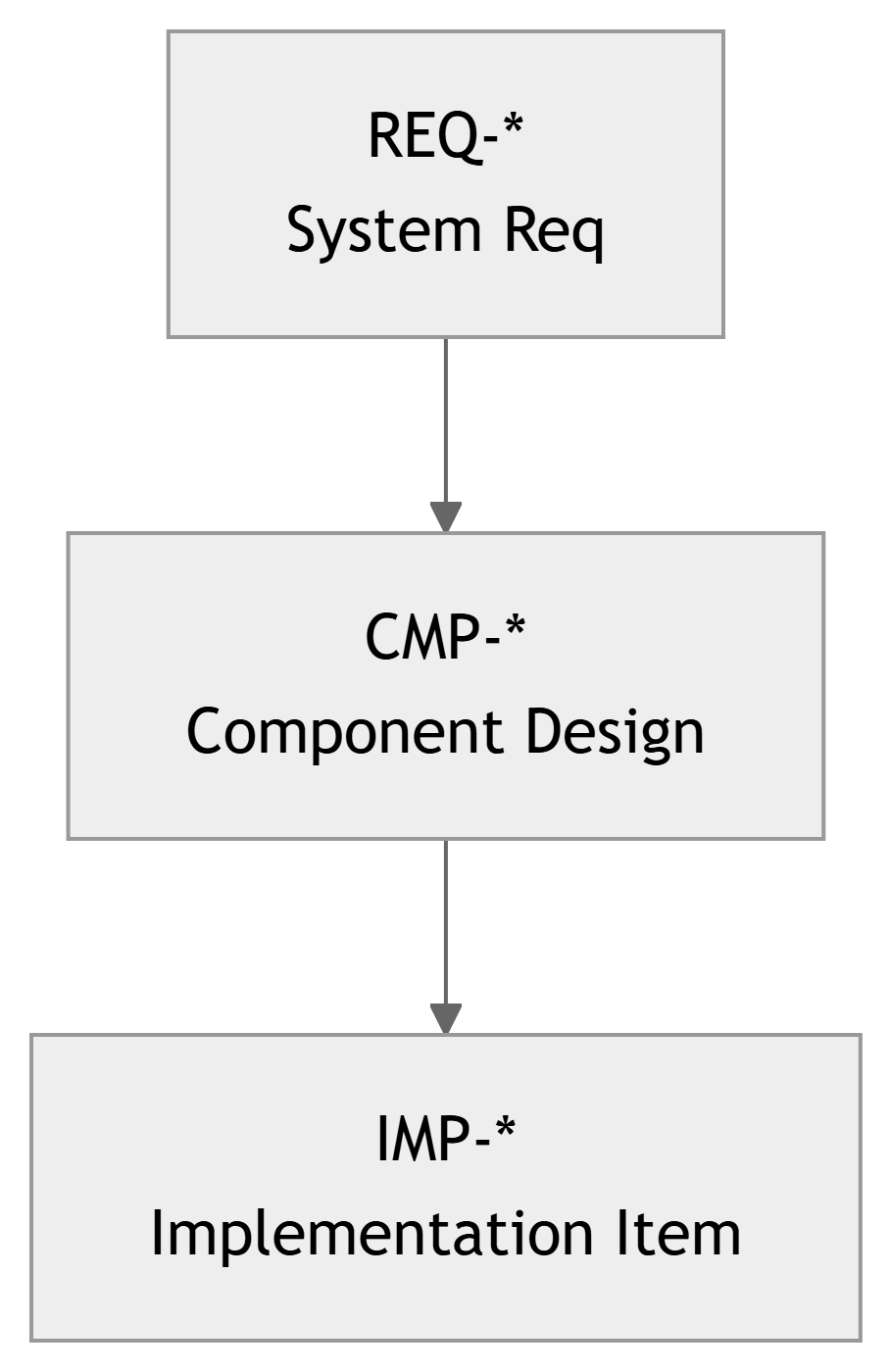
- Implementation status is recorded in the RTM as
REQ-* → CMP-* → IMP-*.
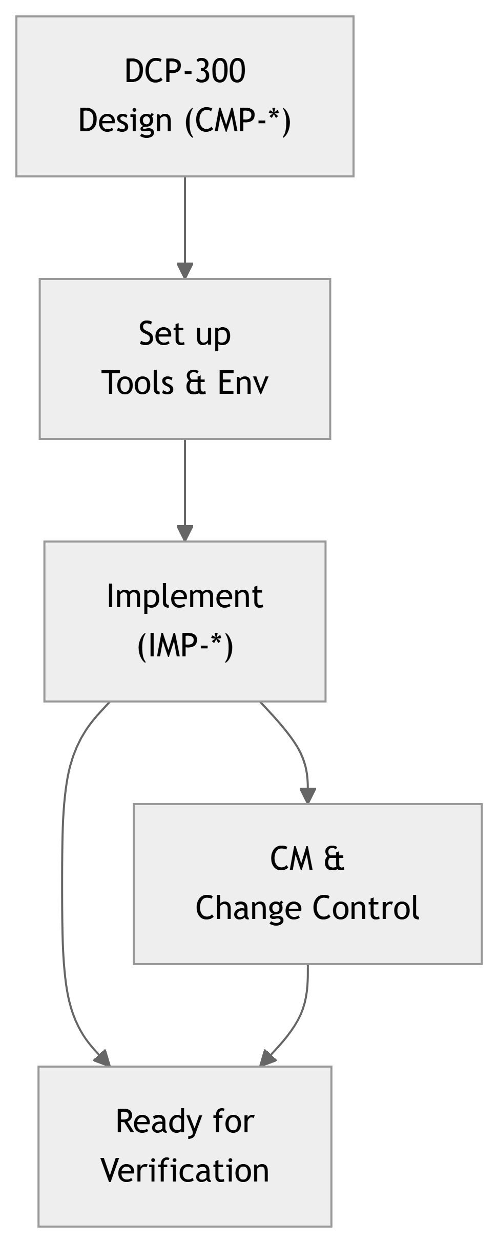
Stage 5 Activities – Big Picture
Key activities in Stage 5:
- Set up the implementation environment
- Toolchains, IDEs, simulators, synthesis tools, PCB vendors, lab benches.
- Implement components (
IMP-*)- Coding firmware/applications/FPGA logic.
- Building and assembling PCBs and hardware prototypes.
- Perform internal checks
- Smoke tests, static analysis, code review, bench bring‑up.
- Manage configurations and changes
- Use Git, track issues, maintain change logs.
- Keep RTM synchronized with evolving implementation.
- Prepare for Unit/System Verification
- Ensure build is repeatable and documented.
- Ensure component implementations match design (
CMP-*).
Example: IMP-* Entries in the RTM
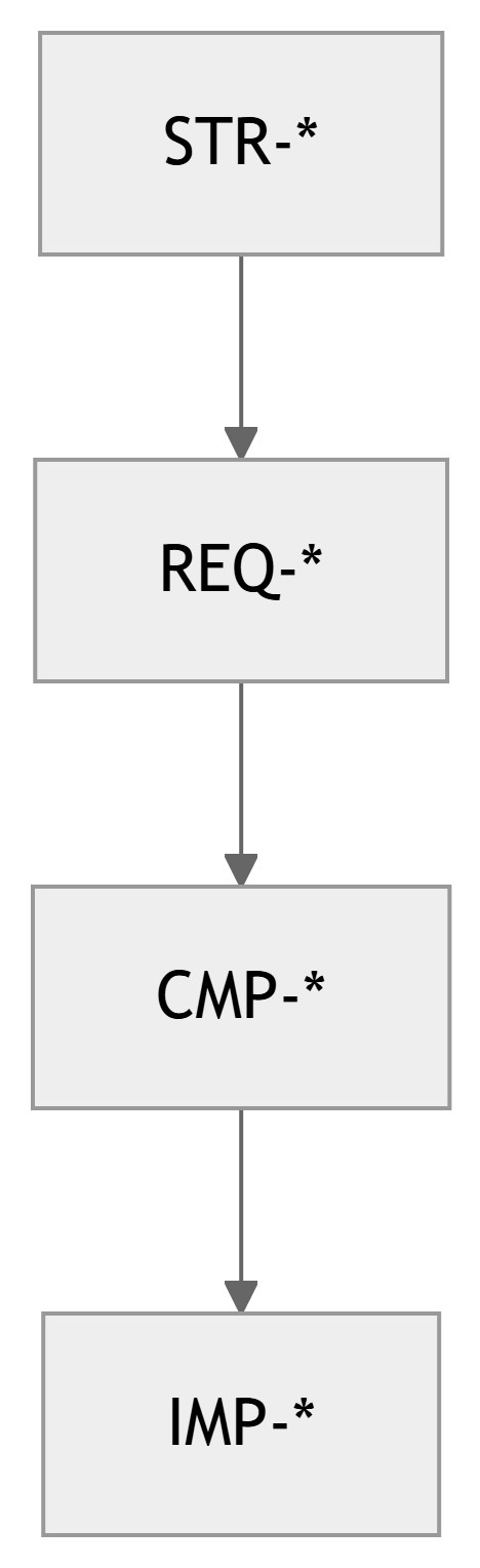
Traceability extension at Stage 5:
Previously:
STR-* → REQ-* → CMP-*
Now we add:
CMP-* → IMP-*
Example rows in RTM:
| CMP ID | IMP ID | Description |
|---|---|---|
| CMP-SW-010 | IMP-SW-010A | UI module (Flutter app) |
| CMP-SW-020 | IMP-SW-020A | Control task (FreeRTOS C module) |
| CMP-SY-030 | IMP-SY-030A | Sensor PCB rev B (KiCad project) |
| CMP-SY-040 | IMP-SY-040A | LoRa gateway firmware (C++) |
Tip
Use IDs in: - Commit messages - Issue tracker - Comments in code (// Implements REQ-SW-015 via CMP-SW-020)
Implementation Workflow – From Design to Code/Boards

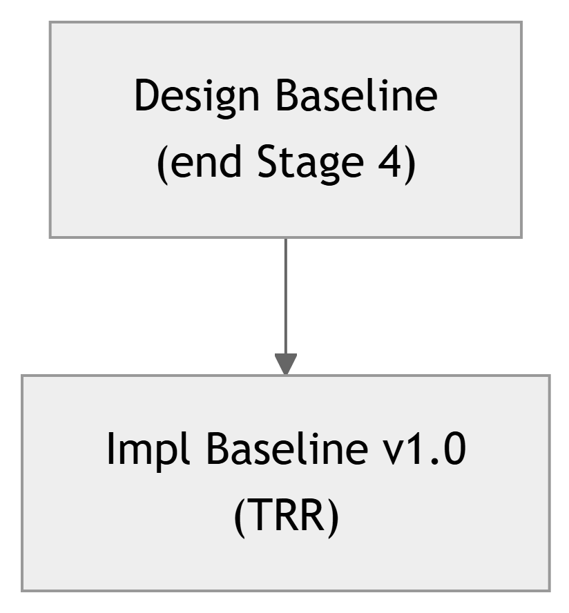
Configuration Baselines in Stage 5
What is a baseline?
A baseline is a formally agreed snapshot of your configuration items (CIs) at a specific time, used as a reference going forward.
Typical baselines at Stage 5:
- Implementation Baseline for TRR (Test Readiness Review):
- Tagged Git commits for firmware, backend, and UI.
- PCB revision and BOM version.
- Documented calibration/config files.
Important
At the Stage 5 Gate (TRR), you must be able to say: > “We are using these exact versions of code, boards, and configs for verification.”
Internal Testing vs Formal Verification
During Stage 5, you will:
- Run quick checks to see if your implementation basically works:
- Power‑on tests.
- Simple functional tests (e.g., “LED blinks”, “UART prints messages”).
- HDL simulations to see waveforms look reasonable.
- Fix defects discovered during bring‑up.
These are sometimes called developer tests or smoke tests.
Formal Verification (Stages 6 & 7):
- Uses planned test cases (
TST-*,VER-*) traceable toREQ-*. - Follows documented procedures.
- Has clearly recorded pass/fail criteria.
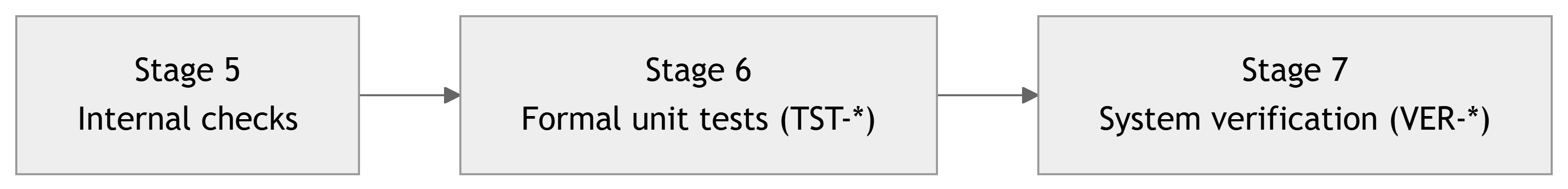
Note
Stage 5 ends when you have implementations stable enough to enter planned verification.