Stage 4 – Architecture & Component Design
Capstone Design
Stage 4 – Architecture & Component Design
From Requirements to a Buildable Design
Capstone Design – Stage 4 Focus Session
This deck covers Stage 4 – Architecture & Component Design in the course V‑Model.
Pre‑requisites for students: - Stage 2 complete: DCP‑100B (Stakeholder Requirements, STR-*). - Stage 3 complete or nearly complete: DCP‑200 (System / SW Requirements, REQ-*).
Goals of this session: - Explain what architecture and component design mean in the context of this course. - Connect to ISO/IEC/IEEE 15288 & 29148 : - Architecture Definition - Design Definition - Requirements Allocation - Show key deliverables (what goes in your Stage 4 design docs ). - Use ECE‑relevant examples (embedded system, FPGA/DSP, networked systems, medical/wearables).
V‑Model – Where Stage 4 Fits
Stage 3 defined what the system must do (REQ-*).Stage 4 defines how the system is structured so those REQ-* can be met.It sets up the units/components you will verify in Stage 6 .
Point out the vertical alignment: - Stage 4’s architecture & design are what Stage 6’s unit tests and Stage 7’s integration tests will target.
If Stage 4 is fuzzy, it becomes hard to say what a “unit” or “component” even is.
Standards Context – 15288 & 29148 in Stage 4
In Stage 4, we mostly apply three processes from the standards:
Architecture Definition (15288)
Identify main system elements and how they interact.
Design Definition (15288)
Refine architecture into detailed component designs sufficient for implementation.
Requirements Allocation (29148/15288)
Allocate system requirements (REQ-SY-*) to specific hardware, firmware, and software components (REQ-HW-*, REQ-SW-*, etc.).
Think of Stage 3 as defining the target . Stage 4 defines the structure of the arrow you will shoot at that target.
Stress that we’re not memorizing these standards; we’re using them as guidance for good engineering practice .
We care that students: - Structure their systems. - Allocate requirements. - Document their designs clearly.
Architecture vs. Detailed Design – Big Picture
Architecture (high level):
Major components (e.g., sensors, gateway, backend, UI).
How they communicate (interfaces, protocols).
Deployment view (what runs where).
Component Design (lower level):
Internal structure of each component (modules, threads, state machines, data flows).
Internal interfaces and data structures.
Algorithms, timing, and resource allocation details.
Architecture answers: > “What are the main parts and how do they connect?”
Component design answers: > “What does each part look like internally?”
ECE analogy: - Architecture ≈ block diagrams in datasheets. - Design ≈ detailed schematics, state machines, pseudo‑code .
Both must be consistent with REQ-* defined in DCP‑200.
Requirements Allocation – What and Why
Requirements Allocation = assigning each system requirement (REQ-SY-*) to:
One or more hardware components (REQ-HW-*), and/or
One or more software components (REQ-SW-*), and/or
Combined behavior of multiple components.
This ensures:
Every REQ-SY-* has a home in the design.
Each component knows what requirements it must satisfy .
You can later verify at the right level (unit vs integration).
Practically: - Make a table: REQ-SY-* → Component(s). - Then, if helpful, derive more specific REQ-HW-* and REQ-SW-*.
Emphasize: Allocation is not just paperwork.
If you don’t allocate requirements, you risk: - Nobody implementing a needed behavior. - Multiple components trying to do the same thing. - Confusion in testing (“who is responsible for this latency?”).
Example: High‑Level Architecture – Smart Lab Sensor Network
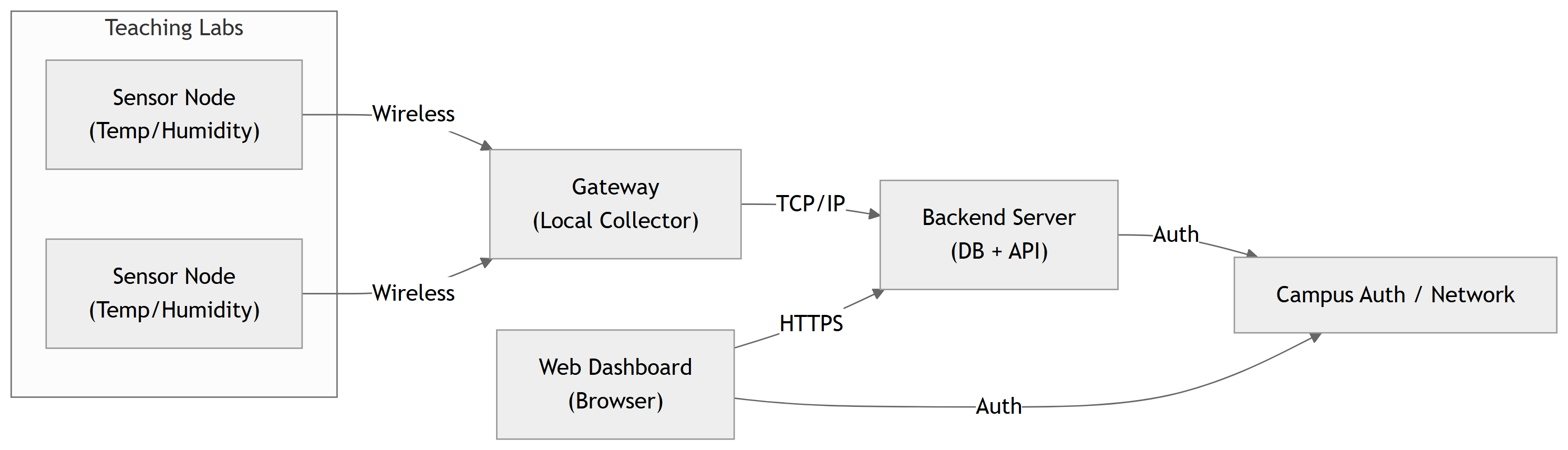
Major elements in this architecture:
Sensor Nodes – embedded hardware for sensing and wireless communication.Gateway – aggregates sensor messages, forwards to backend.Backend Server – data store, application logic, alerts, APIs.Web Dashboard – front‑end for technicians and managers.Campus IT – authentication and network services.
Show how this diagram came from Stage 3 REQ-*: - We needed wireless sensors, a centralized data store, and a web UI. - We also must integrate with campus auth: hence the explicit IT block.
Ask students: - What other architectures could we have used (e.g., no separate gateway, sensors talk directly to cloud)?
Example: Requirements Allocation (Excerpt)
Using the Smart Lab architecture:
REQ-SY-001 – Store latest temp/humidity per lab
Sensor Node, Gateway, Backend DB
REQ-SY-003 – Dashboard refresh every 60 s
Backend API, Web Dashboard
REQ-SY-010 – Create overheat alerts
Backend Alert Logic
REQ-SY-061 – Notify technicians within 120 s
Backend Notification Service, Email/SMS Agent
REQ-SY-060 – Dashboard loads in ≤ 3 s (95% of time)
Backend (performance), Web Dashboard (UI), Network
REQ-SY-092 – Use HTTPS for web access
Web Server / Backend, Campus IT
REQ-SY-081 – Detect missing sensor (“sensor fault”)
Gateway, Backend, Dashboard UI
Allocation helps: - Clarify which component is responsible for each behavior. - Identify cross‑cutting concerns, like performance and security.
Encourage teams to create a full allocation table (maybe in a spreadsheet), even if they don’t put every line in the report.
This also helps them define unit test scopes in Stage 6.
ECE Example – Remote Instrument Lab Architecture
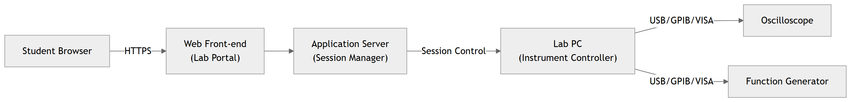
Consider a Remote Electronics Lab system:
Students remotely control benchtop instruments (oscilloscope, function generator) via a web interface.
Possible requirements allocation:
Session management, exclusivity (REQ-SY-104): Application Server .
Instrument command translation: Lab PC Instrument Controller .
User scheduling/booking: Web Front‑end + Application Server .
Ask: - Where do we enforce “only one student per instrument at a time”? - Who is responsible for timing guarantees (e.g., latency)?
This forces them to think about responsibility assignment in architecture.
ECE Example – FPGA‑Based DSP System Architecture
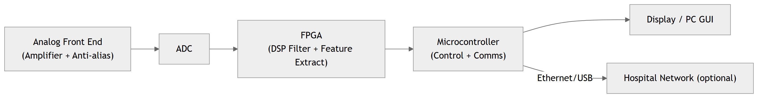
Project: Real‑time ECG filter on FPGA + Microcontroller .
Possible allocation:
Sampling requirements (REQ-HW-100): ADC + FPGA interface .
Filter characteristics (REQ-SW-100): FPGA DSP blocks .
End‑to‑end latency (REQ-SY-101): ADC + FPGA + MCU + UI pipeline .
Logging and configuration: MCU + UI + Network .
Show how architecture clarifies timing budget : - If end‑to‑end latency must be ≤ 100 ms, you can allocate sub‑budgets to each block.
This will later inform design details (e.g., pipeline depth, communication method).
Component Design – Example (Backend Service)
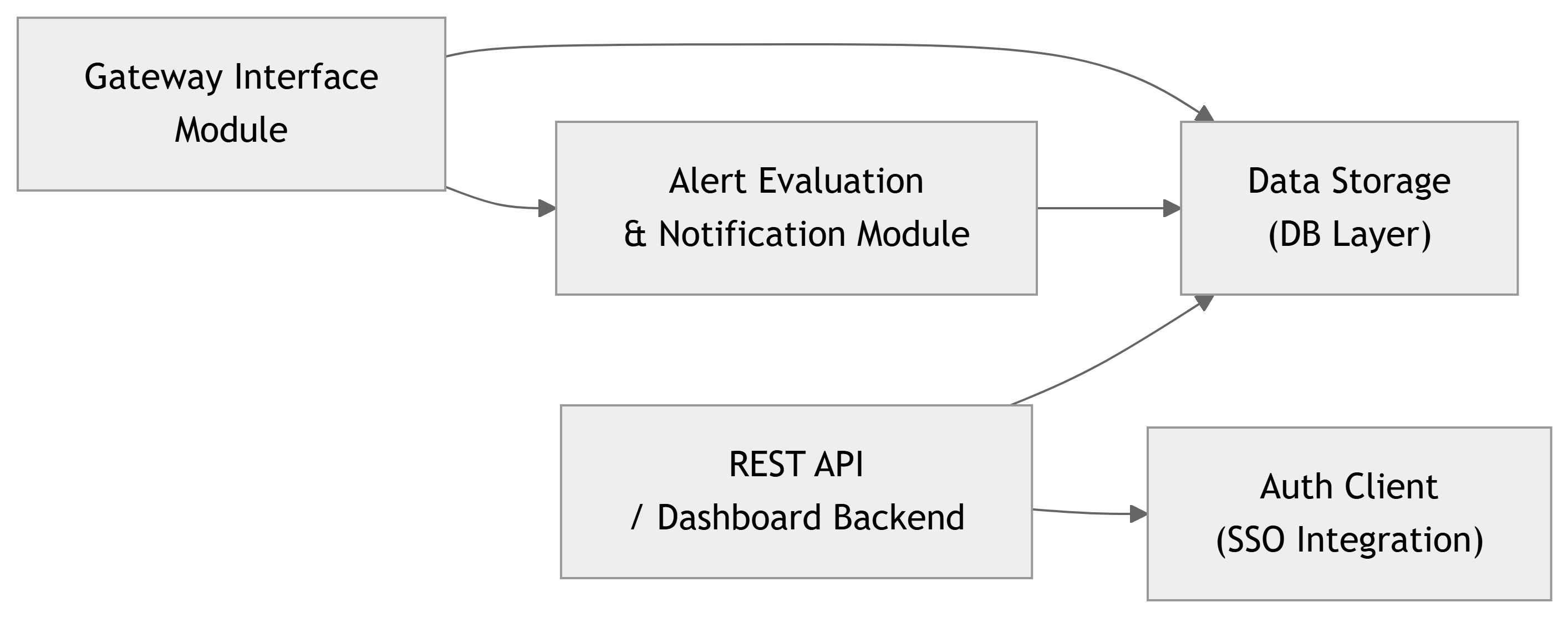
For the Smart Lab system, one architectural element is the Backend Server .
At design level, we can refine it into:
Design decisions to capture:
GW Interface Module :
Protocol used (e.g., TCP, MQTT, custom).
Message formats and parsing logic.
Alert Module :
How thresholds are applied (sliding window? instantaneous?).
How notifications are queued and sent.
API / Auth :
Endpoints, parameters, error codes.
Which endpoints require which roles.
Explain that this level of design helps: - Developers break down coding tasks. - Testers plan unit tests for each module (Stage 6).
Encourage using simple module diagrams , plus text/pseudo‑code for key behaviors.
Component Design – Example (Sensor Node)
For the Sensor Node (embedded microcontroller):
A typical embedded design breakdown:
Hardware:
MCU, sensor chip, power supply, antenna.
Firmware tasks:
Sensor reading task.
Communication task.
Power management task.
High‑level firmware structure (conceptually):
You might capture a state machine :
Idle
Measure
Transmit
Retry
Error
And a register / message format :
Byte 0–1: Node ID
Byte 2–5: Timestamp
Byte 6–7: Temperature * 10 (int16)
Byte 8–9: Humidity * 10 (int16)
Byte 10–11: CRC
Design details like tasks, states, and packet formats are what distinguish Stage 4 design from Stage 3 requirements .
Stress: This is the level at which you can meaningfully assign people tasks and estimate effort.
Also: these design details will support specific unit/integration tests later (e.g., packet parser test, sensor driver test).
Linking Design Back to Requirements
A good Stage 4 design explicitly answers:
For each major component , which REQ-* does it help satisfy?
For each critical requirement , where in the architecture/design is it addressed?
Example (Smart Lab):
Sensor Node Firmware
REQ-HW-001, REQ-HW-060, REQ-HW-061, REQ-SY-030
Gateway
REQ-SY-030, REQ-SY-032, REQ-SY-081
Backend Alert Module
REQ-SY-010, REQ-SY-011, REQ-SY-061
Web Dashboard Front-end
REQ-SW-041, REQ-SW-042, REQ-SW-100, REQ-SW-101
Auth Integration
REQ-SY-090, REQ-SY-050
If you can’t point to any part of your design that fulfills a given REQ-*, either the requirement is missing in the design or mis‑allocated .
Encourage teams to do a quick traceability sanity check before the Stage 4 gate review.
This also helps them spot over‑engineering – components that don’t seem to support any requirements.
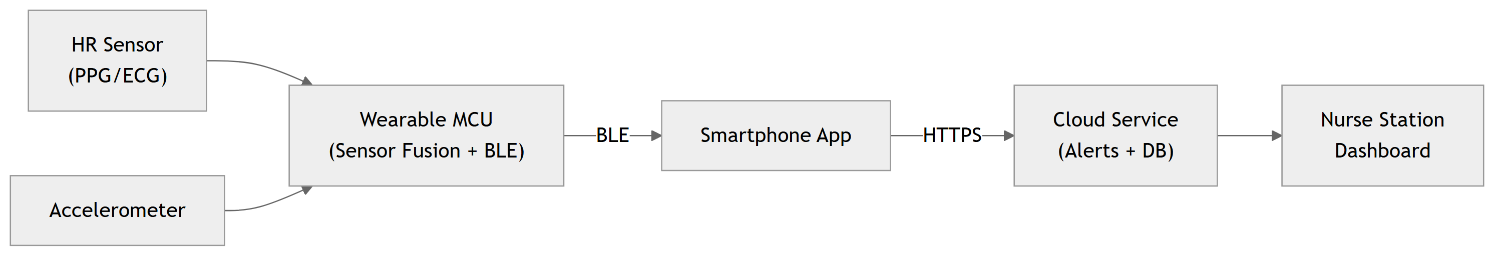
ECE Example – Wearable Health Monitor Design
System: Wearable heart‑rate and activity monitor .
High‑level architecture (simplified):
Design activities:
Decide sampling rates and buffer sizes on the MCU.
Design algorithms for HR and activity detection (e.g., filters, peak detection).
Specify BLE characteristics and messages between wearable and phone.
Define API between phone app and cloud.
Decide where to implement tachycardia detection logic:
On the wearable?
On the phone?
On the cloud?
Each choice affects: - Latency (e.g., REQ-SY-213 – alert within 300 s). - Power consumption, connectivity needs.
Ask: - If connectivity is lost, where can we still detect dangerous conditions? - How do we allocate safety‑critical requirements to the most reliable component?
This is a real architectural design trade‑off.
Common Pitfalls in Stage 4
Jumping straight to code/PCB without shared architecture
Leads to mismatched assumptions and integration pain.
Architecture too vague
“We have a microcontroller and a server” with no clarity on responsibilities or protocols.
Over‑specifying design as requirements
In Stage 3, you may have already locked in implementation details unnecessarily.
No clear mapping from requirements to components
Some REQ-* have no home; some components exist with no purpose.
Ignoring non‑functional aspects in design
Architecture doesn’t consider performance, power, security, or safety until too late.
Stage 4 is where you make big structural decisions . Getting them wrong is expensive to fix later.
Reinforce: It’s okay to iterate, but large changes after Stage 4 can cascade through implementation and tests.
Encourage design reviews : - Within the team, - With advisor, - Possibly with stakeholders for sanity checks.