Capstone Design Course Introduction
Capstone Design
Imron Rosyadi
Capstone Design Course Introduction
From Needs to Validated Systems using the V‑Model & ISO/IEC/IEEE 29148
Document Context: DCP‑000 Course Guide, Rev 1.0
Session Learning Objectives
By the end of this session, you will be able to:
- Explain the overall V‑Model lifecycle used in the course.
- Describe the nine stages of the Capstone project and their main deliverables.
- Explain the difference between verification and validation.
- Use the basic ID and traceability scheme (STR, REQ, CMP, IMP, TST, VER, VAL).
- Understand the DCP document package and gate reviews.
Why a Structured Capstone?
Engineering reality:
- Real systems are complex (HW + SW + users + environment).
- Failing late is expensive (money, safety, reputation).
- Industry uses process models (V‑Model, 29148, 15288) to reduce risk.
Course philosophy:
- Your capstone is a mini‑industry project, not just a demo.
- You will practice the full lifecycle from need → requirements → design → code/hardware → tests → handover.
- We grade both technical quality and engineering discipline.
Real‑world ECE examples:
- Medical device firmware must trace every requirement to a test (FDA).
- Automotive ECUs follow V‑Model (ISO 26262) to prove safety.
- Telecom base stations use detailed requirements / architecture for complex RF + DSP chains.
Important
Key message: You’re learning how real engineering organizations work.
Standards Backbone for the Course
Core standards guiding this course:
ISO/IEC/IEEE 29148:2018 Life cycle processes — Requirements engineering
ISO/IEC/IEEE 15288:2023 System life cycle processes — provides the V‑Model context.
We map the course to these by:
- Structuring stages according to 29148 processes.
- Using the V‑Model as the project roadmap.
- Emphasizing requirements quality, verification, validation, and traceability.
Core Principles of the Capstone
- Requirements before solutions
- Understand the problem and needs before jumping to circuits, code, or schematics.
- Traceability always
- Every artifact (requirement, design element, test) is linked up and down.
- The Requirements Traceability Matrix (RTM) is your single source of truth.
- Verifiable & Validated
- Verification: “Did we build it right?”
- Validation: “Did we build the right thing?”
Tip
Think of requirements like a contract: You can’t claim you met the contract unless each clause is testable and tested.
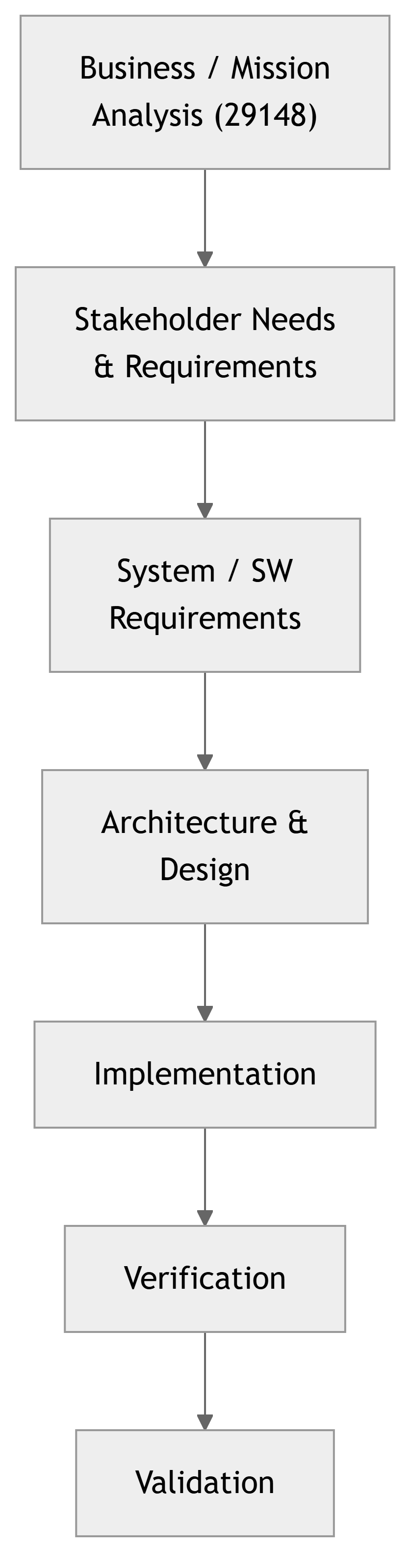
The V‑Model – Big Picture
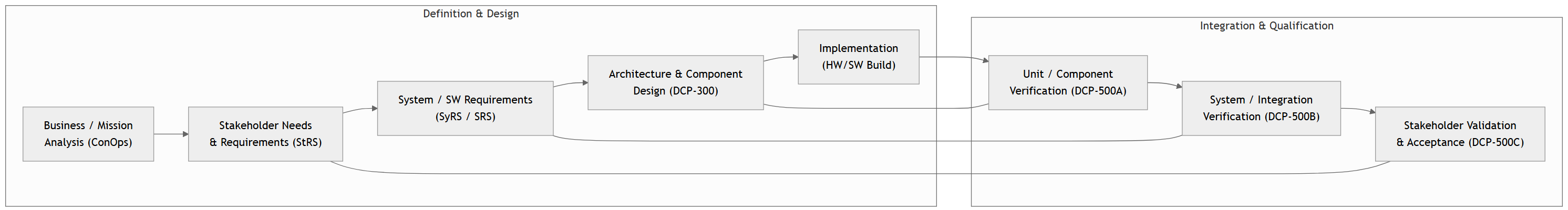
Note
Left side: Define & design.
Right side: Test & prove.
Bottom: Implementation.
Course Stages Overview
We implement the V‑Model in nine stages:
- Project Framing & Concept of Operations (ConOps)
- Stakeholder Requirements
- System Requirements
- Architecture & Component Design
- Implementation
- Unit / Component Verification
- System / Integration Verification
- Stakeholder Validation
- Project Finalization & Handover
Each stage:
- Has a clear purpose.
- Produces a DCP document.
- Is gated by a review before moving on.
DCP Document Package – Your “Engineering Dossier”
| ID | Title | 29148 Item | Gate Review | Typical Due Time |
|---|---|---|---|---|
| DCP‑100A | Project Proposal | ConOps, Stakeholder List | Stage 1 Gate | Week 3 |
| DCP‑100B | Stakeholder Requirements | StRS | Stage 2 Gate | Week 6 |
| DCP‑200 | System Requirements | SyRS | Stage 3 Gate | Week 9 |
| DCP‑300 | Design | Architecture, Design Descr | CDR (Critical Design Rev) | Week 13 |
| DCP‑400 | Implementation | Implementation records | TRR (Test Readiness Rev) | Sem 2 Week 6 |
| DCP‑500A | Unit Verification | Verification Reports | Unit Test Review | Sem 2 Week 8 |
| DCP‑500B | System Verification | Verification Reports | System Test Review | Sem 2 Week 11 |
| DCP‑500C | Stakeholder Validation | Validation Reports | Final Demo | Sem 2 Week 14 |
| DCP‑600 | Final Report & Handover | Final RTM, Manuals, Archive | Final Submission | Finals Week |
Warning
Gate Reviews:
You cannot proceed to the next stage without:
- Approved document
- Updated RTM
- Traceability intact
- Key risks reviewed
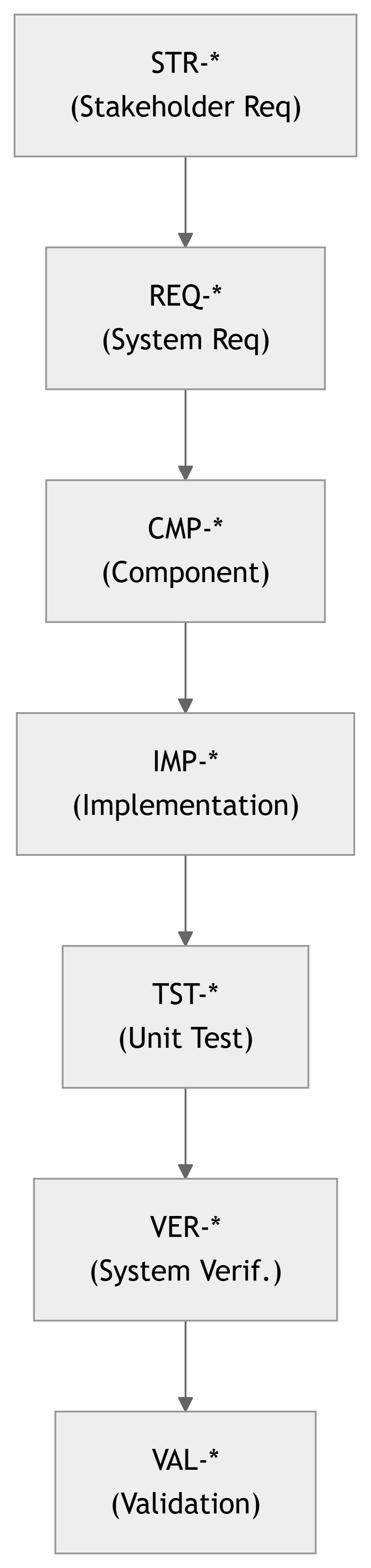
Traceability: The Backbone of the Project
Artifacts and IDs:
- Stakeholder Requirement →
STR-SY-###orSTR-SW-### - System Requirement →
REQ-SY-###orREQ-SW-### - Component →
CMP-SY-###orCMP-SW-### - Implementation Artifact →
IMP-SY-###orIMP-SW-### - Unit Test →
TST-SY-###orTST-SW-### - System Verification Test →
VER-SY-###orVER-SW-### - Validation Activity →
VAL-SY-###orVAL-SW-###
All of these live in the Requirements Traceability Matrix (RTM).
Traceability Links:
Traceability in the V‑Model
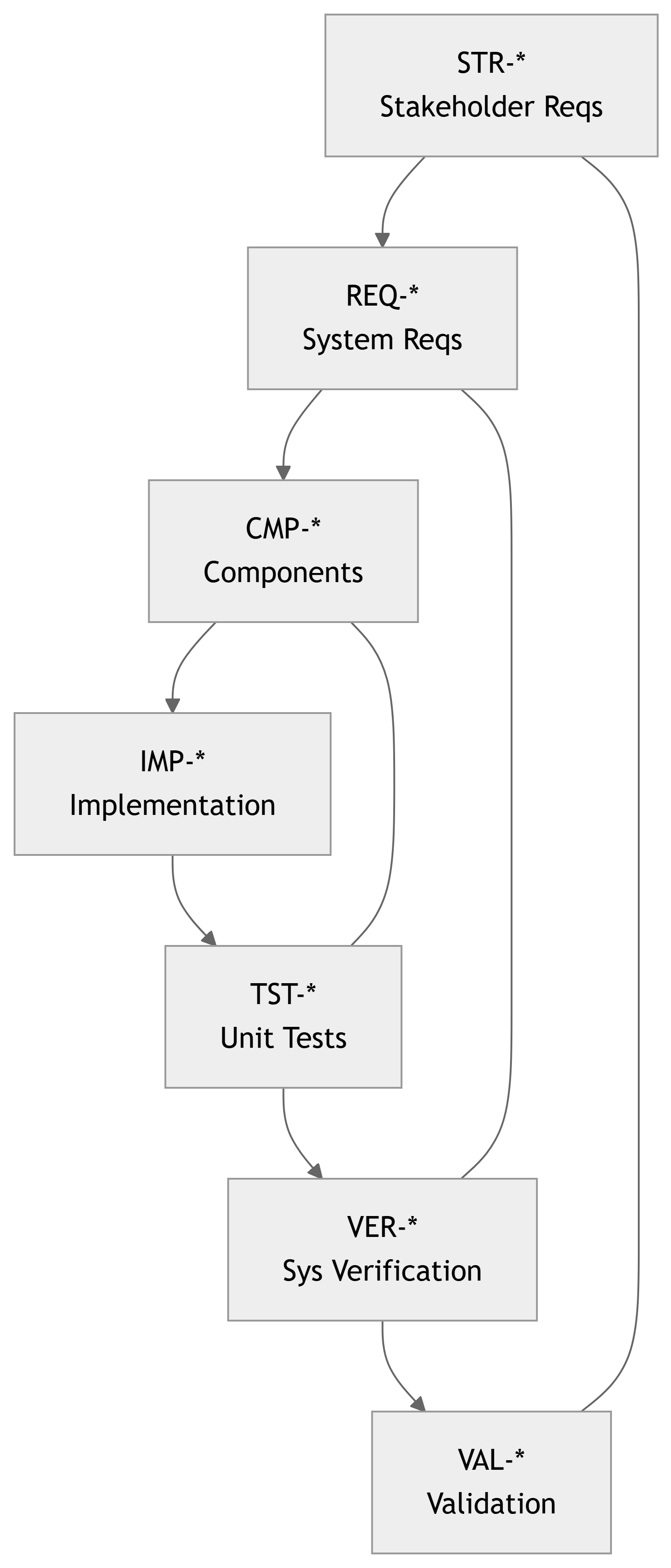
Note
Horizontal links:
STR-* ↔︎ VAL-*(Stakeholder needs ↔︎ Acceptance tests)REQ-* ↔︎ VER-*(System requirements ↔︎ System tests)CMP-* ↔︎ TST-*(Component design ↔︎ Unit tests)
Stage 1 – Project Framing & Concept of Operations
V‑Model Level: Top‑left – Concept / Need
29148 Processes:
- Business or Mission Analysis
- Stakeholder Identification
Capstone Activities:
- Define the problem domain and business/mission need.
- Analyze existing solutions and their limitations.
- Characterize environment: users, constraints, stakeholders.
- Select a solution class (not a detailed design).
- Produce a Concept of Operations (ConOps).
Key Deliverable:
- DCP‑100A Project Proposal
- Problem statement
- Stakeholder map
- Operational scenarios
- High‑level success criteria
Tip
Focus on the “why”, not on schematics or specific chips yet.
Stage 2 – Stakeholder Needs & Requirements
V‑Model Level: Upper‑left – Stakeholder / User Requirements
29148 Processes:
- Stakeholder Needs & Requirements Definition
- Early Requirements Validation (planning)
Capstone Activities:
- Identify all stakeholders: advisors, clients, end‑users, regulators, lab staff.
- Conduct interviews, surveys, observations.
- Use use cases, user stories, and scenarios to elicit needs.
- Prioritize needs (e.g., MoSCoW, Kano).
- Resolve conflicts and negotiate scope.
- Develop a Stakeholder Requirements Specification (StRS).
Key Deliverable:
- DCP‑100B Stakeholder Requirements
STR-*IDs- High‑level acceptance criteria
- Initial Validation Plan (
VAL-*planned)
Quality Criteria (29148):
- Necessary
- Unambiguous
- Complete (to agreed scope)
- Traceable to business needs
Stage 3 – System / Software Requirements
V‑Model Level: Mid‑left – System Requirements
29148 Processes:
- System/Software Requirements Definition
- Requirements Analysis
Capstone Activities:
- Transform stakeholder needs (StRS) into technical requirements.
- Categorize:
- Functional
- Performance
- Interface
- Security
- Usability
- Environmental / Reliability / Safety
- Define acceptance criteria and verification methods:
- Test, Analysis, Model, Demonstration, Inspection (TAMDI).
- Ensure requirements are:
- Verifiable, Feasible, Singular (one requirement per statement).
- Produce SyRS/SRS.
Key Deliverable:
- DCP‑200 System Requirements
REQ-*IDs- Bidirectional traceability:
STR-* → REQ-* - Initial Verification Plan (
VER-*planned)
Example requirement form:
\[ \text{REQ-SY-023: The system shall}~ <\text{observable behavior}> \\ \text{under}~ <\text{conditions}> ~\text{with}~ <\text{quantitative criteria}>. \]
Stage 4 – Architecture & Component Design
V‑Model Level: Mid‑left – Architecture and Detailed Design
29148 / 15288 Role:
- Architecture Definition
- Design Definition
- Requirements Allocation
Capstone Activities:
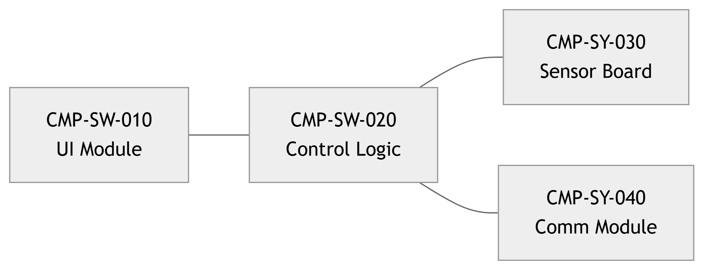
- Develop system architecture:
- Block diagrams
- Data flow, control flow, or state diagrams
- Allocate each
REQ-*to one or more components (CMP-*). - Define interfaces (signals, protocols, voltages, APIs).
- Develop detailed design:
- Algorithms, data structures (SW)
- Schematics, PCB layouts (HW)
- Update RTM:
REQ-* → CMP-*.
Key Deliverable:
- DCP‑300 Design
- Architecture views
- Component specifications (
CMP-*) - Requirements Allocation Matrix
- Initial Test Plan (
TST-*planned)
Important
Every component should exist because it satisfies at least one requirement. If you can’t map a component to a requirement, question why it exists.
Stage 5 – Implementation / Construction
V‑Model Level: Bottom – Coding / Building
29148 / 15288 Role:
- Implementation Process
- Configuration Management
Capstone Activities:
- Implement the design:
- Develop software modules (embedded, apps, services).
- Build hardware (prototypes, PCBs, mechanical assemblies).
- Use version control (Git) and branching strategies.
- Perform code / design reviews against requirements.
- Manage change requests when implementation forces requirement/design updates.
Key Deliverable:
- DCP‑400 Implementation
- Implementation artifacts (
IMP-*) - Build procedures
- Updated requirements baseline & change log
- Implementation artifacts (
Note
Expect iterative build–test–fix cycles.
The key is to manage changes and keep traceability up to date.
Stage 6 – Unit / Component Verification
V‑Model Level: Lower‑right – Unit Testing / Component Verification
29148 Process: Verification at component level
Capstone Activities:
- Design and execute unit tests for each component (
CMP-*). - Map each test (
TST-*) to:- Component(s)
- Allocated requirements (
REQ-*)
- Record test procedures, environments, and results.
- Log defects and perform root‑cause analysis.
- Update RTM:
CMP-* → TST-*.
Key Deliverable:
- DCP‑500A Unit Verification
TST-*test cases- Unit test logs
- Defect reports
Tip
For every test case, be able to answer:
“Which requirement does this verify?”
Stage 7 – System / Integration Verification
V‑Model Level: Mid‑right – Integration & System Test
29148 Process: Verification against system requirements
Capstone Activities:
- Integrate components incrementally (e.g., bottom‑up, top‑down, or mixed).
- Test interfaces and interactions (timing, protocols, data consistency).
- Execute system test procedures derived from SyRS/SRS.
- Ensure full coverage of
REQ-*in system verification. - Update RTM:
REQ-* ↔︎ VER-*.
Key Deliverable:
- DCP‑500B System Verification
VER-*system test cases and results- Integration & system test reports
- Updated RTM with coverage metrics
Important
Verification = “Did we build it right?” Does the integrated system meet all system requirements?
Stage 8 – Stakeholder Validation & Acceptance
V‑Model Level: Top‑right – System / Acceptance Testing
29148 Process: Validation
Capstone Activities:
- Execute system‑level tests against stakeholder needs (StRS).
- Conduct acceptance testing with real stakeholders.
- Observe users in realistic environments or scenarios.
- Ask:
“Does this system solve the original business/mission problem?”
- Gather feedback, capture issues or change requests.
- Produce Validation Report and Acceptance Sign‑off.
Key Deliverable:
- DCP‑500C Stakeholder Validation
VAL-*validation activities and results- Stakeholder demo summary
- Lessons learned from usage
Important
Validation = “Did we build the right thing?” Even a perfectly verified system can fail validation if it doesn’t meet real needs.
Stage 9 – Project Finalization & Handover
V‑Model Level: Spans entire V – Transition & Closure
29148 / 15288 Processes:
- Information Management
- Transition
- Disposal Planning (at least conceptually)
Capstone Activities:
- Finalize all documentation:
- StRS, SyRS/SRS
- Design docs
- Test reports
- User & maintenance manuals
- Freeze and archive the Requirements Traceability Matrix (RTM).
- Conduct a project post‑mortem (lessons learned).
- Present final system to faculty, sponsors, and stakeholders.
Key Deliverable:
- DCP‑600 Final Report & Handover
- Complete RTM
- Project archive (source, CAD, configs)
- Handover instructions
Note
Think like a professional engineer handing a system to a client or another engineering team.
Teaching Topics by Stage (Roadmap)
| Stage | Focus Topics |
|---|---|
| 1 | Problem scoping, stakeholder analysis, ConOps, problem vs solution space, systems thinking |
| 2 | Elicitation techniques, characteristics of good StRS, use cases, MoSCoW, ambiguity review |
| 3 | Functional vs non‑functional, 29148 requirement characteristics, TAMDI verification methods, constraints |
| 4 | Architecture views, requirement allocation, interfaces, make/buy, design rationale |
| 5 | Configuration management, baselines, change control, technical debt, integration planning |
| 6 | Unit test design, code coverage, requirement‑based testing, defect tracking |
| 7 | Integration strategy, system test design, emergent properties, test environments |
| 8 | Validation planning, usability testing, stakeholder feedback, “fit for purpose” |
| 9 | Documentation, handover, maintenance planning, post‑mortem, ethics |
Example: Smart Lab Sensor Network (ECE Context)
Concept:
Design a wireless sensor network that monitors temperature and humidity in teaching labs and pushes data to a dashboard.
Sample Stakeholder Requirements (STR-*):
STR-SY-001: Lab technicians shall monitor each lab’s temperature in real time from a central dashboard.STR-SY-002: System shall alert staff when temperature in any lab exceeds 28°C for more than 10 minutes.
Derived System Requirements (REQ-*):
REQ-SY-010: Each sensor node shall measure temperature from 10–40°C with ±0.5°C accuracy.REQ-SY-011: Each node shall transmit measurements at least once every 60 s.REQ-SW-020: The server software shall generate an alert within 2 min of detecting a lab exceeding 28°C for 10 min.
Potential Tests (TST-*, VER-*, VAL-*):
TST-SY-001: Bench‑test temperature sensor calibration.VER-SW-002: System‑level test of data latency and alert generation.VAL-SY-001: Validation session with lab staff to confirm alerts are useful and understandable.
Summary – What You Should Take Away Today
- The course uses the V‑Model and ISO/IEC/IEEE 29148 to structure your capstone.
- You will work through nine stages from problem framing to handover.
- Traceability is central:
STR-* → REQ-* → CMP-* → IMP-* → TST-* → VER-* → VAL-*. - DCP documents (DCP‑100A … DCP‑600) are your official artifacts for gate reviews.
- Verification asks: “Did we build it right?” Validation asks: “Did we build the right thing?”
Important
Your success is not just the final demo. It is demonstrating that you can engineer a system professionally, from needs to validated solution.